
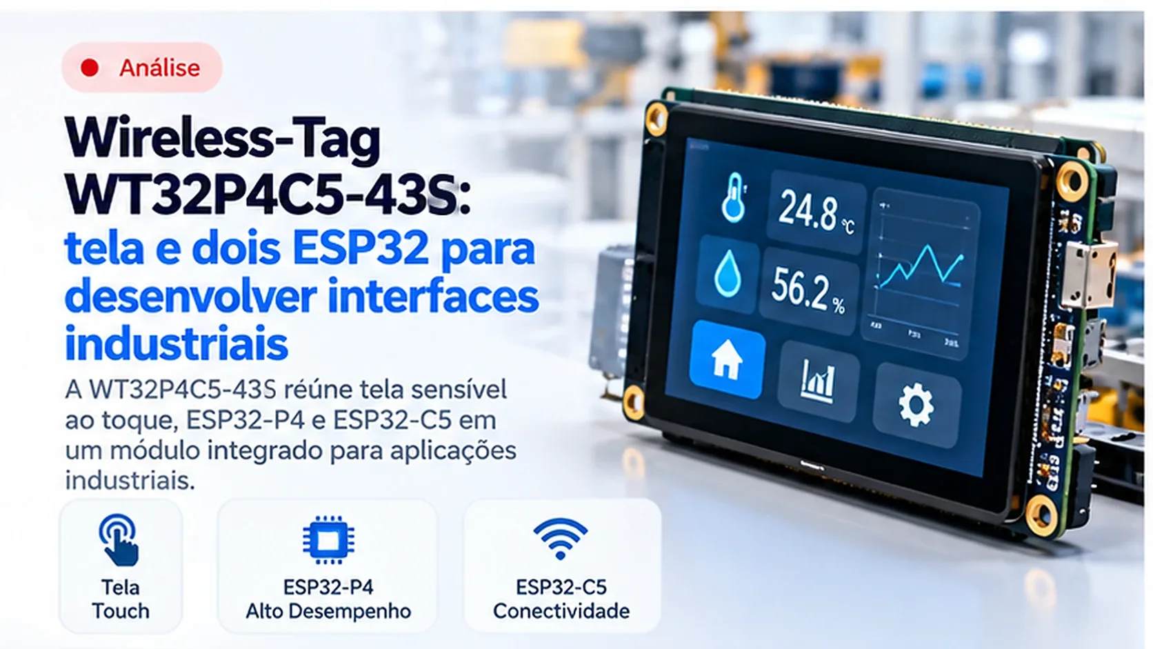
Wireless-Tag WT32P4C5-43S: a display and two ESP32 chips for developing industrial interfaces
The WT32P4C5-43S brings together a touchscreen, ESP32-P4 and ESP32-C5 on a development board. For those building connected panels, this integration simplifies initial assembly and introduces an important task: coordinating the graphical interface and communication between two processors.
Text generated automatically from the official sources listed below, without line-by-line human editorial review. Found an error? Tell the community.
In short
For those developing connected panels, our assessment is that the Wireless-Tag WT32P4C5-43S simplifies the start of prototyping by bringing together a display and wireless communication. It combines ESP32-P4, ESP32-C5 and a 4.3-inch touchscreen. Those keeping equipment running in the field do not need to change anything because of this release. For those developing a product, the work involves integrating the programs running on the two chips.
What it is
The WT32P4C5-43S is a development board: a collection of components prepared for experimenting with functions and building applications before designing the final equipment. What Wireless-Tag has introduced is the combination of the two microcontrollers and the display in a single assembly. Microcontrollers are chips that run programs and control the circuits connected to them. The configuration was described by CNX Software.
In this architecture, the ESP32-P4 acts as the main processor, while the ESP32-C5 provides wireless connectivity. The assembly offers Wi-Fi 6 in the 2.4 and 5 GHz bands. Wi-Fi 6 is a generation of wireless local area networking technology; the frequency band indicates the region of the spectrum in which the radio operates. The choice between bands depends on the infrastructure and signal propagation at the site.
A human-machine interface, or IHM, is the part of the equipment through which the operator monitors values and sends commands. The display is only one part of it. The interface also includes the rules that distinguish a current measurement from old information, present alarms and confirm whether a command was executed.
What it is for
A board with an integrated display lets development start with the application's behavior: navigation, status indication and data exchange. The developer can evaluate whether the operator can find the necessary information before investing in a custom board. In connected systems, this evaluation needs to include operation during a network outage.
Consider an example project: a panel for monitoring temperature and the status of a pump. The data can arrive through MQTT, a messaging protocol in which devices publish information to channels called topics. An intermediary server, known as a broker, receives these messages and distributes them to interested subscribers. The panel turns the messages into understandable values, trends and notifications.
In this example, displaying the last temperature received is insufficient. The application must also store when the data arrived and indicate when it has become stale. A start command needs its outcome confirmed by the equipment responsible for actuating the motor. Delivery of a message does not prove that the motor has started running.
Where it is used
Embedded interfaces are used in operator stations, benchtop instruments, utility systems and local maintenance points. In an industrial installation, they can present information close to the machine while the SCADA, a supervisory control and data acquisition system, provides a centralized view of the process. These are typical uses of this class of technology, not reports of installations using the announced board.
Another common architecture connects a panel to instruments through Modbus, a protocol that organizes data reads and writes as registers. In its serial RTU mode, it commonly uses RS-485, an electrical standard for differential communication suited to wired networks. The protocol defines the conversation; the RS-485 circuit carries the signals over the cable.
Building this connection from a microcontroller requires a transceiver, a component that converts electrical signals between the chip and the bus. The design also needs to consider termination, biasing, grounding and protection against electrical disturbances. In installations with potential differences between equipment, galvanic isolation breaks the direct conductive path and helps protect the interface.
Relevance for industry
Editorial view: the appeal of the WT32P4C5-43S lies in shortening the initial assembly of a connected interface. I would include it in the evaluation of projects that need local operation and wireless communication, starting with a prototype representative of the process. The success criterion would be clarity and recovery of operation in the face of failures, in addition to the appearance of the display.
In automation, the panel must represent the actual state of the system. If communication drops, the interface needs to report that condition and handle pending commands explicitly. Automatically resending an old request after reconnection can produce an action the operator no longer expects. Commands therefore need rules for validity, confirmation and handling repetitions.
The 5 GHz band adds an option for network planning, but the decision should be based on measurements at the installation point. Metal structures, machines and antenna placement affect coverage. For a mobile interface or a maintenance terminal, mobility may justify a wireless network; for functions with strict timing requirements, the communication architecture needs to be defined based on those requirements.
Impact on embedded systems
Editorial view: developing with two processors requires treating internal communication as a formal product interface. My recommendation for this kit is to define from the outset how the main program identifies the radio module's state, detects a restart and restores message exchange. This prevents a connectivity failure from leaving the display looking normal but without valid data.
Firmware is the software executed by the device. When different firmwares cooperate, they need to agree on message formats and operating states. Bounded queues, response deadlines and message identification help control the flow. Display updates must continue working while a communication task attempts to restore the connection.
ESP-IDF is Espressif's collection of libraries and tools for developing these programs. Reproducing a project also depends on the components used to control the board and on the build tools. In PlatformIO, an environment that organizes builds, dependencies and flashing, this configuration should be recorded alongside the code. The microcontroller's name alone does not define a complete board configuration.
For the final hardware, the initial integration does not complete the electrical and mechanical design. Power supply, heat dissipation, connectors, display mounting and maintenance access need to be evaluated together. The update interface must also allow the equipment to be recovered after an interruption, including when only one of the processors has received the new firmware.
Limits and what is still missing
The supplied sources do not demonstrate industrial qualification of the assembly, performance under graphical load and simultaneous traffic, or a validated path for integration with PlatformIO. They also do not establish an RS-485 interface ready for field use. These points need to be confirmed before turning the prototype into a purchasing specification or a product.
There is a specific concern regarding security features of the chips involved. The primary release note from Espressif for ESP-IDF v5.5.6 records the removal of Key Manager support on the ESP32-P4 and ESP32-C5 because this peripheral requires design changes before it can be offered as a production feature. Key Manager is the block intended for managing cryptographic keys. This information is a basis for reviewing security dependencies; it does not prove that this version of ESP-IDF is compatible with the Wireless-Tag board, nor does it mean that all other protection mechanisms are absent.
My recommendation is to follow the board-specific documentation and examples, especially the version combination of the two firmwares. Before adopting the assembly, turn the open questions into verifiable criteria. What to do now:
- Define which data the panel displays, when it becomes stale and how commands are confirmed. - Record the combination of tools, libraries and firmwares that reproduces the prototype. - Test network loss, restart of each processor and power interruption during an update. - Check the electrical interfaces, protection, mounting and security features required by the product.