
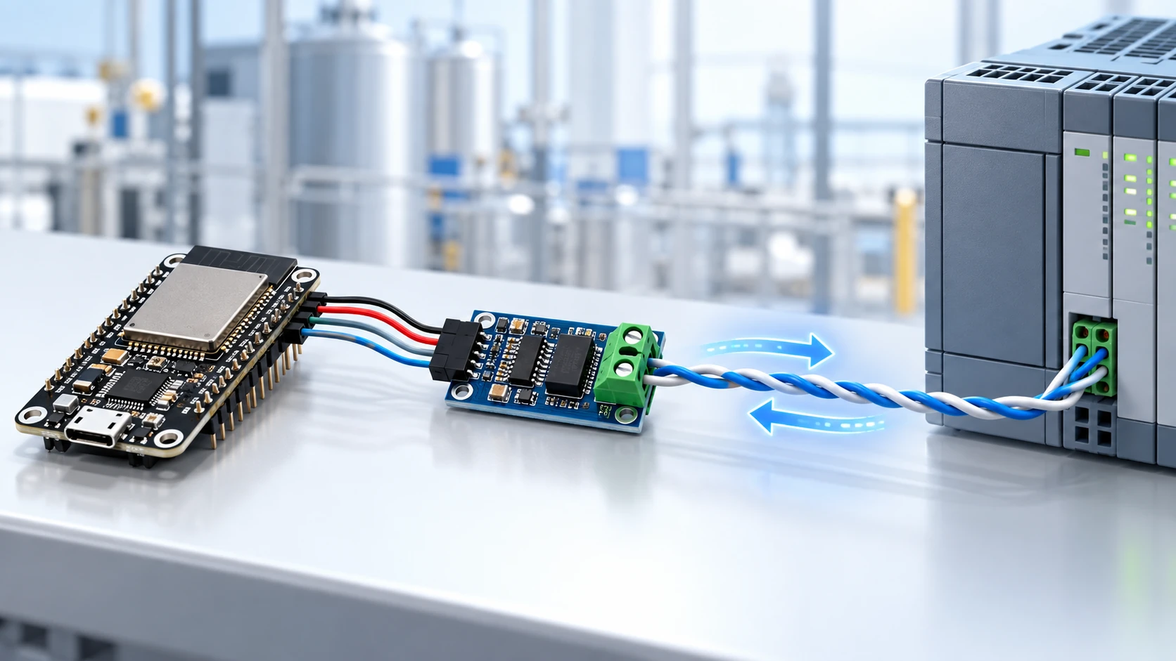
Modbus RTU over RS-485 on the ESP32
Read Modbus RTU registers on the ESP32 without a library: DE/RE control, CRC16, the 3.5-character silence between frames and 120-ohm termination.
Hardware requirements:
- Placa ESP32 ou ESP32-S3
- Transceiver RS-485 (MAX3485 ou SP3485; MAX485 exige divisor no RO)
- Dois resistores de 120 ohms para terminação
- Par trançado, de preferência com blindagem
- Um escravo Modbus RTU: multimedidor, inversor ou CLP
Download this tutorial's materials:
- Projeto completo (ZIP)130 KBFirmware Arduino com o protocolo Modbus implementado do zero: CRC16, montagem do quadro, leitura com tempo limite e diagnóstico traduzido. README e manual em PDF.
- Manual em PDF (7 páginas)156 KBAs três armadilhas do Modbus em microcontrolador, passo a passo, regras de terminação do barramento, tabela de exceções e checklist final.
Want to receive new manuals and industrial schematics? Join our channel on Telegram / WhatsApp
Why Modbus RTU still matters
Modbus RTU dates back to 1979 and is still what ships in energy meters, variable-frequency drives, pressure transmitters and temperature controllers. Not because it is elegant, but because it is simple enough for a cheap microcontroller and stable enough to run for twenty years in a control panel.
Reading these devices with an ESP32 costs only a few dollars in components and solves the problem behind half of IIoT projects: the data exists, it is in the panel, and it goes nowhere.
This tutorial implements the protocol directly, without a library. Not out of purism — libraries hide exactly the three details that make communication fail, and you need to understand all three when the bus stops responding.
RS-485 is not an ordinary serial port
The first conceptual mistake is treating RS-485 as UART with a different connector.
On ordinary serial, each side has its own transmit wire. RS-485 has one pair of wires, shared by every device, and information is represented by the voltage difference between them. That is why it can cross hundreds of meters in an environment full of motors and drives, where ordinary serial would not make it ten.
The consequence is that only one device can talk at a time. There is no detectable collision and no arbitration. The master asks, the slave answers, and nobody else speaks during that interval. Everything else in this article follows from that.
The transceiver and the pin that decides everything
The MAX485 converts the ESP32 UART to the differential pair. It has four control pins, and two of them perform the same job with inverted logic:
DI receives what the ESP32 transmits, and RO delivers what arrives from the bus. DE enables the transmitter high, and RE enables the receiver low.
Because you never want to transmit and receive at the same time, the usual pattern is to tie DE and RE to the same GPIO. High means talk, low means listen. One less wire and no chance of leaving both enabled by mistake.
| 1 | ESP32 GPIO17 (TX) -> DI |
| 2 | ESP32 GPIO16 (RX) <- RO |
| 3 | ESP32 GPIO4 -> DE e RE juntos |
| 4 | 3V3 -> VCC |
| 5 | GND -> GND |
Use a 3.3 V transceiver such as the MAX3485 or SP3485. The classic MAX485 is a 5 V part: it often works powered at 3.3 V, but RO may still output a level above what the ESP32 can tolerate. If you use the 5 V part, add a divider on RO.
Mistake number one: releasing DE too early
This is the most common bug and the hardest one to see.
The temptation is to write to serial and disable DE on the next line. But write does not wait for the data to leave — it only queues it in the UART buffer. If you lower DE immediately, the transmitter turns off in the middle of the frame and the slave receives a truncated message without ever replying.
The correct approach is to wait for the UART to empty before releasing it:
| 1 | void modbusEnviar(const uint8_t *quadro, size_t tamanho) { |
| 2 | digitalWrite(PINO_DE_RE, HIGH); |
| 3 | delayMicroseconds(50); |
| 4 | Serial2.write(quadro, tamanho); |
| 5 | Serial2.flush(); |
| 6 | delayMicroseconds(50); |
| 7 | digitalWrite(PINO_DE_RE, LOW); |
| 8 | } |
flush is the important line: it blocks until the last bit leaves the shift register. The two 50-microsecond waits give the transceiver time to switch — some parts need a few microseconds between enabling and the output becoming stable.
If your slave never replies and you have already checked the wiring and address, this is almost always the cause.
The 3.5-character silence
Modbus RTU has no start or end-of-frame marker. The message is delimited by silence time: a pause equivalent to 3.5 characters marks the end, and a pause longer than 1.5 characters in the middle invalidates what came before it.
That means the time depends on the baud rate. With 8N1, each character takes 10 bits:
| 1 | 9600 bps 1 caractere = 1,042 ms silencio = 3,65 ms (calculado) |
| 2 | 19200 bps 1 caractere = 0,521 ms silencio = 1,82 ms (calculado) |
| 3 | 38400 bps 1 caractere = 0,260 ms silencio = 1,75 ms (fixo por norma) |
| 4 | 115200 bps 1 caractere = 0,087 ms silencio = 1,75 ms (fixo por norma) |
Notice the turning point: above 19200 the standard abandons the calculation and fixes 1.750 ms. The calculated value would be shorter than the typical processing time of a slave — at 115200 it would be 0.3 ms, too short for many devices to react. Using the calculated value at these speeds produces unstable communication with slow slaves.
In practice, respecting this means waiting through the silence before sending the next request. Chaining requests without a pause is the second most common cause of corrupted responses.
CRC16 and the byte-order trap
Modbus uses CRC16 with polynomial 0xA001, calculated over every byte in the frame. It takes ten lines:
| 1 | uint16_t modbusCRC(const uint8_t *dados, size_t tamanho) { |
| 2 | uint16_t crc = 0xFFFF; |
| 3 | for (size_t i = 0; i < tamanho; i++) { |
| 4 | crc ^= dados[i]; |
| 5 | for (uint8_t bit = 0; bit < 8; bit++) { |
| 6 | if (crc & 0x0001) { |
| 7 | crc = (crc >> 1) ^ 0xA001; |
| 8 | } else { |
| 9 | crc >>= 1; |
| 10 | } |
| 11 | } |
| 12 | } |
| 13 | return crc; |
| 14 | } |
The trap is that the CRC is placed in the frame with the least significant byte first, unlike the rest of the protocol, which is big-endian. The address and register quantity put the high byte first; the CRC is reversed. Getting this wrong produces a frame that looks perfect and is never accepted.
Building a register read
Function 03 reads holding registers, which is what 90% of devices use. The frame has eight bytes:
| 1 | uint8_t construirLeitura(uint8_t *quadro, uint8_t escravo, |
| 2 | uint16_t inicio, uint16_t quantidade) { |
| 3 | quadro[0] = escravo; |
| 4 | quadro[1] = 0x03; |
| 5 | quadro[2] = inicio >> 8; |
| 6 | quadro[3] = inicio & 0xFF; |
| 7 | quadro[4] = quantidade >> 8; |
| 8 | quadro[5] = quantidade & 0xFF; |
| 9 | uint16_t crc = modbusCRC(quadro, 6); |
| 10 | quadro[6] = crc & 0xFF; |
| 11 | quadro[7] = crc >> 8; |
| 12 | return 8; |
| 13 | } |
Notice the CRC in the final two lines: low part first, high part second. It is the reversal described above.
The manual's address is not the protocol address
This is the third trap and the one that consumes the most time for beginners.
The device manual may say that phase A voltage is in register 40001. In the protocol, that register is number 0. The 4xxxx numbering is a documentation convention, not what goes into the frame.
The rule is to subtract 40001 from the number in the manual. 40001 becomes 0, 40011 becomes 10 and 40100 becomes 99.
Some manufacturers document zero-based addresses already, and a few mix both conventions. If the reading has a plausible value but the wrong magnitude, try shifting one register in either direction before suspecting the code.
Reading the response with a timeout
The response contains the same address, the same function, the byte count and the data:
| 1 | bool modbusLer(uint8_t escravo, uint16_t inicio, |
| 2 | uint16_t quantidade, uint16_t *saida) { |
| 3 | uint8_t quadro[8]; |
| 4 | uint8_t tamanho = construirLeitura(quadro, escravo, inicio, quantidade); |
| 5 | while (Serial2.available()) Serial2.read(); |
| 6 | modbusEnviar(quadro, tamanho); |
| 7 | uint8_t esperado = 5 + quantidade * 2; |
| 8 | uint8_t resposta[64]; |
| 9 | uint8_t recebidos = 0; |
| 10 | unsigned long limite = millis() + 300; |
| 11 | while (millis() < limite && recebidos < esperado) { |
| 12 | if (Serial2.available()) { |
| 13 | resposta[recebidos++] = Serial2.read(); |
| 14 | } |
| 15 | } |
| 16 | if (recebidos < esperado) return false; |
| 17 | if (resposta[0] != escravo) return false; |
| 18 | if (resposta[1] & 0x80) return false; |
| 19 | uint16_t crc = modbusCRC(resposta, recebidos - 2); |
| 20 | if ((crc & 0xFF) != resposta[recebidos - 2]) return false; |
| 21 | if ((crc >> 8) != resposta[recebidos - 1]) return false; |
| 22 | for (uint16_t i = 0; i < quantidade; i++) { |
| 23 | saida[i] = (resposta[3 + i * 2] << 8) | resposta[4 + i * 2]; |
| 24 | } |
| 25 | return true; |
| 26 | } |
Three checks that many implementations skip: clearing the buffer before sending discards stale bytes from earlier reads; checking bit 0x80 in the function detects an exception response, where the slave says the address does not exist or the value is invalid; and checking the response CRC prevents accepting data corrupted by noise, which is not a remote possibility in an electrical panel.
Termination: the 120 ohms are not optional
On a long bus, the signal reaching the end reflects back and interferes with the next bit. The result is communication that works on the bench and fails in the panel, or works with one device and stops when you connect a second.
The fix is a 120-ohm resistor between A and B at both ends of the bus — only at the ends, never on devices in the middle. Many modules include the resistor or a jumper; if your ESP32 is in the middle of the line, remove it.
You also need idle biasing: when nobody transmits, the line floats and the receiver can interpret noise as data. 680-ohm resistors pulling A to positive and B to ground solve it. Some transceivers include this internally.
The pair must also be twisted. Two parallel wires cancel the advantage of differential signaling, whose purpose is to pick up the same interference on both conductors.
Tutorial: from the bench to the first reading
Step 1: connect the transceiver
With everything powered off, connect the RS-485 module according to the transceiver section's table. Confirm that DE and RE are tied to the same GPIO — on most modules this is a jumper or an existing trace.
Power the transceiver at 3.3 V, not 5 V, unless you added a divider on RO.
Step 2: connect the slave
Connect the module's A and B to the device's A and B, respecting polarity. Manufacturers differ in naming: some use D+ and D-, others A and B, and some invert the convention.
If it does not respond, swap A and B before changing the code. It is free and solves many cases.
Also connect the reference ground between both sides. RS-485 is differential, but both sides must remain within the same common-mode voltage range.
Step 3: find the slave parameters
You need four pieces of information, all in the manual or device display: the slave address (1 to 247), baud rate, parity and the register you want to read.
The most common setting is 9600 8N1, but 19200 and even parity are also common. Start with what the manual says; without a manual, 9600 8N1 at address 1 is the best guess.
Step 4: configure platformio.ini
Create the file at the project root:
| 1 | [env:esp32-modbus] |
| 2 | platform = espressif32 |
| 3 | board = esp32dev |
| 4 | framework = arduino |
| 5 | monitor_speed = 115200 |
There are no external libraries: the protocol is implemented in the file itself.
Step 5: adjust the code parameters
At the top of the firmware, set the address, baud rate and register to the values found in step 3. Remember to subtract 40001 from the number in the manual.
Start by reading a single register. A large quantity makes it harder to separate a parameter error from a communication error on the first attempt.
Step 6: flash and observe
Build, upload and open the monitor:
| 1 | pio run -t upload |
| 2 | pio device monitor -b 115200 |
A successful read prints the raw value. Compare it with the value on the device display: if the number matches, or is an exact multiple of 10 or 100, you found the right register — the scale factor is documented in the manual.
If the value has no relation to the display, the register is wrong. Return to step 3.
Step 7: interpret the scale
Modbus transports 16-bit integers. A meter displaying 127.3 V will often return 1273, with the factor documented in the manual.
Values above 65535, such as accumulated energy, occupy two registers. Read both and combine them: the lower address is usually the high part, but some manufacturers reverse it. If the number jumps absurdly, try the opposite order.
Common errors and solutions
The slave never replies. In order: reverse A and B; confirm flush happens before lowering DE; check the address and baud rate; check the reference ground.
It replies sometimes and sometimes does not. Termination is missing, or requests are being chained without respecting the 3.5-character silence.
CRC is always invalid. The CRC byte order is almost certainly reversed — the low part goes first.
The response has bit 0x80 set in the function. This is a slave exception, not your error: the next byte gives the reason. Code 02 means a nonexistent register address, the most frequent case.
The value does not match the display. Wrong register or scale. Check the 40001 offset and the factor in the manual.
It works with one device and stops with two. Terminate only the two ends and use different addresses for each slave.
Noise appears when the drive starts. Use shielded twisted pair, ground the shield at one end only and keep the cable away from power cables. If it persists, lower the baud rate: 9600 is much more tolerant than 38400.