
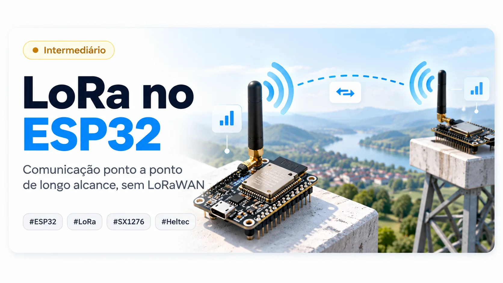
LoRa on the ESP32: long-range point-to-point communication, without LoRaWAN
Two Heltec WiFi LoRa 32 V2 boards talking across hundreds of meters: SF, bandwidth and time on air, what we measured in the lab, the antenna, crystal and ACK traps, and packet loss by sequence number.
Hardware requirements:
- Duas placas Heltec WiFi LoRa 32 V2 (ESP32 + SX1276), versão 915 MHz, com antena
- Dois cabos USB e o PlatformIO
Download this tutorial's materials:
- Projeto completo (ZIP)14 KBEmissor e receptor para duas Heltec WiFi LoRa 32 V2 (RadioLib, PlatformIO), com a pinagem e os parâmetros do rádio num só arquivo, README e manual em PDF. Os dois programas compilam; não foram rodados em placa.
- Manual em PDF (5 páginas)13 KBSF, banda e tempo no ar, as nove armadilhas, pinagem da Heltec V2, o que medimos em laboratório, tabela de problemas e checklist.
Want to receive new manuals and industrial schematics? Join our channel on Telegram / WhatsApp
LoRa is not Wi-Fi with more range
The ESP32's Wi-Fi covers a room, a house, a small shed. When the sensor sits on the other side of the yard, at the water tank at the back of the property, or in a well with no power and no router, Wi-Fi runs out, and that is where LoRa comes in: a long-range, low-power radio that carries a few bytes over hundreds of meters, and across kilometers in open country.
The price is speed. LoRa is a radio modulation (from Semtech) that trades data rate for sensitivity: you send a few dozen bytes at a time, now and then, at a rate that ranges from hundreds of bits per second to a few kilobits. It suits temperature, level, counts, a door state, an alarm. It does not suit photos, audio, large firmware updates, or anything that depends on a quick back-and-forth conversation.
Two confusions trip up beginners, so let us clear them early:
- LoRa is not LoRaWAN. LoRa is the radio layer. LoRaWAN is a network protocol on top of it, with gateways, a server, keys and usage rules. In this article you work with plain LoRa, from one ESP32 to another, with no gateway and no account on any service. It is the simplest way to understand the radio, and it fits many field projects.
- LoRa has no delivery confirmation. You transmit into the air and whoever is listening with the same parameters receives. If the packet is lost, nobody tells you. Anyone who needs a guarantee builds one: a sequence counter and, if needed, a reply.
What is inside the math: spreading factor, bandwidth and time on air
Three parameters define the radio's behavior, and both sides must use the same ones, or they will not understand each other:
- Spreading factor (SF, from 7 to 12). The higher it is, the more sensitive the receiver and the longer the range, and the much slower the packet.
- Bandwidth (BW). 125 kHz is the common choice. Wider is faster but hears less far.
- Coding rate (CR). Redundancy against errors, from 4/5 to 4/8. More redundancy tolerates more interference and costs more time.
What surprises people most is the time on air. For a 20-byte packet with 125 kHz bandwidth and CR 4/5, Semtech's formula gives:
- SF7: about 57 ms, or roughly 5.5 kbps
- SF8: about 103 ms
- SF9: about 185 ms
- SF10: about 371 ms
- SF11: about 741 ms
- SF12: about 1.3 s, or roughly 300 bps
Each SF step doubles the time on air. That matters in three places: battery (the radio transmitting is what drains most), the chance of colliding with other devices, and spectrum usage rules. Pick the lowest SF that still closes the link, not the highest out of caution.
The traps that burn a weekend
1. Transmitting without an antenna. A LoRa module's output amplifier was built to see an antenna. Transmitting without one sends the energy back into the chip itself and can damage it. Connect the antenna before powering the board, always.
2. The module's frequency. There are 433, 868 and 915 MHz modules, and the difference lies in impedance matching and filtering: it is not just changing a number in the code. Many cheap boards come from European shops, at 868 MHz. In Brazil, both the module and the code must sit in the 915 MHz band. Check what is printed on the board before buying and before configuring.
3. Mismatched parameters. SF, bandwidth, CR, frequency and the sync word must be the same on both sides. One different bit and the receiver stays silent, with no error at all.
4. The power supply. The current peak during transmission is high for a sensor, on the order of a hundred milliamps at maximum power. A weak supply, thin wire or a regulator at its limit brings the ESP32 down at the moment it transmits, and the symptom is a reboot that only shows up when the radio fires. A capacitor near the module helps. In our tests, the node (ESP32 with Wi-Fi and radio on) had peaks of 250 to 350 mA, and a node on a weak supply rebooted (brownout) in the middle of a configuration change. Watch out for some power banks too: they switch off by themselves when consumption falls below 50 to 100 mA, and a low-power node is exactly that.
5. The SPI pins. The radio talks to the ESP32 over SPI, and the chip select, interrupt (DIO0) and reset pins must be exactly the ones the code declares. Every board has its own: the Heltec WiFi LoRa 32 V2 does not use the ESP32's default SPI pins, and the V3 even changes the radio chip. Read your board's schematic instead of copying numbers from another tutorial.
6. Spectrum usage rules. The 915 MHz band is regulated. Use suitable equipment, with power within what the regulation allows for your application, and check the current rules before installing anything in the field. In Europe, the 868 MHz band has a limit on time on air per hour (the 1% duty cycle); in Brazil the rules are different, but the good practice holds anywhere: transmit only what is needed.
7. Anyone can listen. Whoever has a receiver with the same parameters reads everything you transmit. Plain LoRa neither encrypts nor authenticates anything. Do not send sensitive data, and do not let a field command (turn on a pump, open a door) depend on a packet anyone can copy and replay.
8. The crystal that is not a TCXO. The Heltec V2's crystal is not temperature-compensated, and two different boards end up with their frequencies slightly shifted from each other. We measured a difference of about 8 kHz between the two, some 8.7 ppm. With 125 kHz of bandwidth the receiver tolerates about ±31 kHz and this goes by unnoticed. With narrower bandwidths, such as 62.5 kHz, the margin halves and drift with temperature in the field starts to matter. Anyone chasing the theoretical 3 dB gain of a narrower band needs to correct the frequency (AFC) or use modules with a TCXO.
9. The ACK wait time. If you acknowledge packets, the wait for the ACK must follow the SF. The SX1276 only reports "packet received" after demodulating the last symbol, and a symbol lasts 1 ms at SF7 and about 33 ms at SF12. A fixed 150 ms margin, which works at SF7, gets tight at a high SF and causes retransmissions. In our project, 30 to 40% of packets were retransmitted until we made the margin follow the symbol; afterwards, 8 commands out of 8 went through with no retransmission at all.
What you need
- Two Heltec WiFi LoRa 32 V2 boards: ESP32, SX1276 radio and OLED display in one piece, in the 915 MHz version, with one antenna each
- Two USB cables and PlatformIO, as in the first steps in VS Code article
Since the radio is already soldered to the board, there is no wire to connect. What exists is the internal pinout between the ESP32 and the SX1276, and it is what the code must declare:
- SCK on GPIO 5, MISO on GPIO 19, MOSI on GPIO 27
- NSS (chip select) on GPIO 18
- DIO0 on GPIO 26 and DIO1 on GPIO 35
- RESET on GPIO 14
This pinout is for the V2. Other Heltec versions (the V3, for example) bring a different radio chip and different pins: read your board's schematic before copying the numbers. If you use a loose module, such as the RFM95W, wire the same signals to free ESP32 pins and adjust the constants.
Code: the project
The library used is RadioLib, which covers the SX127x and SX126x chips with the same interface. The platformio.ini:
| 1 | [env:heltec-v2] |
| 2 | platform = espressif32 |
| 3 | board = heltec_wifi_lora_32_V2 |
| 4 | framework = arduino |
| 5 | monitor_speed = 115200 |
| 6 | lib_deps = |
| 7 | jgromes/RadioLib@^7.0.0 |
The parameters both sides share sit at the top of each program, and they must be identical:
| 1 | #include <Arduino.h> |
| 2 | #include <SPI.h> |
| 3 | #include <RadioLib.h> |
| 4 | const int PIN_SCK = 5; |
| 5 | const int PIN_MISO = 19; |
| 6 | const int PIN_MOSI = 27; |
| 7 | const int PIN_NSS = 18; |
| 8 | const int PIN_RST = 14; |
| 9 | const int PIN_DIO0 = 26; |
| 10 | const int PIN_DIO1 = 35; |
| 11 | const float FREQ_MHZ = 915.0; |
| 12 | const float BW_KHZ = 125.0; |
| 13 | const uint8_t SF = 9; |
| 14 | const uint8_t CR = 5; |
| 15 | const uint8_t SYNC_WORD = 0x12; |
| 16 | const int8_t POTENCIA_DBM = 10; |
| 17 | SX1276 radio = new Module(PIN_NSS, PIN_DIO0, PIN_RST, PIN_DIO1); |
This board's SPI uses pins different from the ESP32 default, hence the SPI.begin() with explicit pins before starting the radio. The 10 dBm power is on purpose: on the bench, with the two modules one meter apart, maximum power only saturates the receiver.
Code: the transmitter
The transmitter sends a sequence number and the ESP32's internal temperature, just to have data that changes:
| 1 | uint32_t seq = 0; |
| 2 | void setup() { |
| 3 | Serial.begin(115200); |
| 4 | SPI.begin(PIN_SCK, PIN_MISO, PIN_MOSI, PIN_NSS); |
| 5 | int st = radio.begin(FREQ_MHZ, BW_KHZ, SF, CR, SYNC_WORD, POTENCIA_DBM, 8); |
| 6 | if (st != RADIOLIB_ERR_NONE) { |
| 7 | Serial.printf("radio.begin falhou: %d\n", st); |
| 8 | while (true) delay(1000); |
| 9 | } |
| 10 | radio.setCRC(true); |
| 11 | } |
| 12 | void loop() { |
| 13 | char msg[32]; |
| 14 | snprintf(msg, sizeof(msg), "%lu,%.1f", (unsigned long)seq, temperatureRead()); |
| 15 | int st = radio.transmit(msg); |
| 16 | Serial.printf("[TX] %s -> %s (%d)\n", msg, st == RADIOLIB_ERR_NONE ? "ok" : "falhou", st); |
| 17 | seq++; |
| 18 | delay(10000); |
| 19 | } |
transmit() blocks until the packet is out, which takes hundreds of milliseconds at SF9. For a demonstration, that is fine. In a project with other tasks, transmission should stay out of the main loop.
Code: the receiver
The receiver has no waiting loop: the module signals on the DIO0 pin when a packet arrives, and the loop only handles the signal. It is the same principle as the MQTT reconnection article: nothing blocks the firmware waiting for the world.
| 1 | volatile bool chegou = false; |
| 2 | uint32_t ultimaSeq = 0; |
| 3 | uint32_t perdidos = 0; |
| 4 | bool primeiro = true; |
| 5 | void IRAM_ATTR aoChegarPacote() { |
| 6 | chegou = true; |
| 7 | } |
| 8 | void setup() { |
| 9 | Serial.begin(115200); |
| 10 | SPI.begin(PIN_SCK, PIN_MISO, PIN_MOSI, PIN_NSS); |
| 11 | int st = radio.begin(FREQ_MHZ, BW_KHZ, SF, CR, SYNC_WORD, POTENCIA_DBM, 8); |
| 12 | if (st != RADIOLIB_ERR_NONE) { |
| 13 | Serial.printf("radio.begin falhou: %d\n", st); |
| 14 | while (true) delay(1000); |
| 15 | } |
| 16 | radio.setCRC(true); |
| 17 | attachInterrupt(digitalPinToInterrupt(PIN_DIO0), aoChegarPacote, RISING); |
| 18 | radio.startReceive(); |
| 19 | } |
And the packet handling, counting losses from the sequence number:
| 1 | void loop() { |
| 2 | if (!chegou) return; |
| 3 | chegou = false; |
| 4 | String texto; |
| 5 | int st = radio.readData(texto); |
| 6 | if (st == RADIOLIB_ERR_NONE) { |
| 7 | uint32_t seq = strtoul(texto.c_str(), nullptr, 10); |
| 8 | if (!primeiro && seq > ultimaSeq + 1) perdidos += seq - ultimaSeq - 1; |
| 9 | primeiro = false; |
| 10 | ultimaSeq = seq; |
| 11 | Serial.printf("[RX] %s rssi=%.0f snr=%.1f perdidos=%lu\n", texto.c_str(), radio.getRSSI(), radio.getSNR(), (unsigned long)perdidos); |
| 12 | } else if (st == RADIOLIB_ERR_CRC_MISMATCH) { |
| 13 | Serial.println("[RX] pacote corrompido (CRC)"); |
| 14 | } else { |
| 15 | Serial.printf("[RX] erro %d\n", st); |
| 16 | } |
| 17 | radio.startReceive(); |
| 18 | } |
Two things are worth a comment. RSSI is the received power in dBm, and the more negative it is, the weaker the signal. SNR is the signal-to-noise ratio: LoRa decodes signals below the noise, so a negative SNR, within the limits of the SF, still works. And the startReceive() at the end reopens the ear: without it, the module receives one packet and goes deaf.
Tutorial: from zero to the first packet
Step 1. Assemble the two sets, with an antenna on each module, and leave the boards about two meters apart.
Step 2. Flash the transmitter program on one board and the receiver on the other. If you build both in the same project, use two environments in platformio.ini, each with its own main file.
Step 3. Open each board's serial monitor. On the transmitter, every ten seconds:
| 1 | [TX] 0,41.7 -> ok (0) |
| 2 | [TX] 1,41.9 -> ok (0) |
On the receiver, what proves the link:
| 1 | [RX] 0,41.7 rssi=-52 snr=9.8 perdidos=0 |
| 2 | [RX] 1,41.9 rssi=-53 snr=9.5 perdidos=0 |
Your RSSI values will vary; what matters is that the packet shows up with the same numbers as the other board.
Step 4. What to do if nothing arrives. The transmitter prints "ok" and the receiver writes nothing: check, in this order, identical parameters on both sides (frequency, SF, bandwidth, CR and sync word), antennas connected, and the module on the right frequency. If radio.begin fails with an error, the problem is the SPI: the error code and the pinout tell you where to look, and a chip that does not answer is usually a loose wire, power or a wrong pin.
Step 5. Measure the real range. Take the receiver far away, with the antenna vertical, and keep moving off while watching the RSSI and the lost count. In an environment with obstacles, real range is much shorter than in the brochures, which measure in open country with line of sight. Record the results for your terrain. One caution: RSSI only exists when a packet arrives. At SF12, with one send per minute, the number on the screen only changes once a minute and the range test looks frozen. During the walk, send every few seconds (about 8 s) and go back to the normal interval afterwards: in our tests this takes about 30% of the time on air and draws more current.
Step 6. Change the SF. Raise the SF from 9 to 11 on both sides and compare the lowest RSSI at which the packet still arrives. You will see the range gain and its cost: time on air quadruples compared with SF9, and the battery feels it.
What we measured in the lab with two Heltec V2
These numbers come from a project of our own with two Heltec V2 boards (915 MHz), in lab tests and not in a real installation. They hold for that environment and that antenna, not as a promise for yours:
- Typical SX1276 sensitivity with 125 kHz and CR 4/5: about −123 dBm at SF7, −129 dBm at SF9, −134 dBm at SF11 and −137 dBm at SF12.
- Time on air: a 56-byte packet takes about 100 ms at SF7 and 2.6 s at SF12.
- Range (lab test, not field): with one board inside a building and the other carried on foot, horizontal range went from about 50 m at SF7 to about 150 m at SF12, three times more. The theoretical calculation for an indoor environment predicted about 3.7 times. The urban environment with obstacles was far below the kilometers of the brochures.
- The limit shows in the numbers: at the farthest point the RSSI went past −128 dBm and the SNR reached −20 dB, which is the limit of SF12. That is where the link dropped.
- Channel noise: about −121 dBm, with almost no time above −105 dBm: a clean channel.
- RSSI refresh: in the SF12 profile the node sent every 60 s (plus about 20 s of retries) and the signal refreshed every 62 s. With a walk mode that sends about every 8 s, it refreshed every 10 s (between 9 and 14 s), six times faster, at the cost of about 30% of the time on air. A moving average giving the new packet a 25% weight delayed it even more; raising it to 50% helped.
- Changing the SF over the air (one board sends the command, the other switches): from SF7 to SF12 it worked, each change in 2 to 4 s, with an automatic return to the previous profile if the confirmation does not arrive.
What this teaches, in order: the SF helps and costs time on air; the environment matters more than the SF; and every timer in your protocol (ACK, retry, "node offline") must follow the time on air of the chosen SF.
When something does not work
Reboot every time it transmits. The supply cannot handle the current peak. Use a better supply, shorter wires and a capacitor at the module.
Packets arrive with an invalid CRC. Interference, a poor antenna or a link at its limit. Move closer, change the antenna, raise the SF.
It worked one day and stopped. A loose or corroded antenna, a weak battery or another device on the same frequency. Measure the RSSI again and compare it with the first test.
The receiver keeps reporting losses. It could be a collision with another transmitter, a receiver deaf for lack of startReceive(), or a link at its limit. Increasing the interval between packets lowers the chance of collision.
What this article does not cover
- LoRaWAN. Gateway, network server, keys and the regional frequency plan (in Brazil, AU915). It is the path when there are many devices and the internet in the middle, and deserves an article of its own.
- Acknowledgment and retransmission. The sequence counter detects the loss but does not fix it. An ACK back, with a timeout and a retry, is the next step, and trap 9 shows why the timeout must follow the SF. It is also the moment to think about how much time on air your project can afford.
- Packet encryption and authentication. Needed when the data or the command matters. The ESP32 has hardware AES acceleration, which helps.
- Low power. An ESP32 in deep sleep waking only to transmit is what makes a battery last months, and it depends on careful power design.
A note on honesty
What is said about the radio (range, sensitivity, time on air, crystal, ACK, power supply) comes from a project of our own tested in the lab on two Heltec WiFi LoRa 32 V2 boards, in ESP-IDF with a custom driver, not from a brochure. It was a lab test: there is not yet validation in a field installation. The example code in this article is different: a minimal Arduino version using the RadioLib library, written to be read, and, although the kit version compiles with PlatformIO for both programs (transmitter and receiver), it was not run on a board. Function names may change between library versions. Before taking it to the field, compile it in your environment, confirm your module's pinout and measure the range on your terrain. The references to regulation are general guidance: the current Anatel rule is what governs.
To carry the received data further, the receiver can publish over MQTT, as in the ESP32 publishing data to Mosquitto article, and with TLS if the network is not trusted. And for the transmitter to survive failures, see the watchdog.